This is written as a (believe it or not) Perl script, and the code is
straightforward, simple, and reliable. It's running on Windows XP, as
it requires a computer that's so old that it still has a parallel
port! This has become as problem as Win XP is long out of
maintenance, and can no longer be used reliably for a permanent
server. (It's still running rock-steady, but I'm afraid of
it's vulnerability to viruses.)
Unfortunately, I have not been able to get Win10 to run on this
ancient computer. I did buy a parallel port card for a newer
computer, but the only one I could find uses a non-standard I/O
setting instead of 0x378 and I can't seem to get the Perl Device::
library to work with it. Note that I was able to find a test
app DowntownDougBrown
Perallel Port Tester
(local copy) that
shows that it physically works, I simply can't get the Perl code
to talk to it. But that's Ok, it's time to get rid of that
entire computer, screen, keyboard and mouse mess, for a nice little
power-efficient standalone Raspberry Pi.
So the goal of this page is to document my upgrade to using an RPi as a controller. If I get a chance, I'll put in data here on the old Parallel port project as I go.
Note that this page is shown in archeological order, namely newest first. If you want to understand the events in order, start at the bottom.
apt install ntp (may already be installed)systemctl enable ntp/etc/rc.conf:ntpd_enable="YES"ntpd_sync_on_start="YES"
Edit /etc/resolvconf.conf and add "8.8,8.8" as the first
nameserver, then reboot. I was actually having a name resolution
problem to ntp.org; just try doing a ping and see error.
raspi-config
Parallel port version.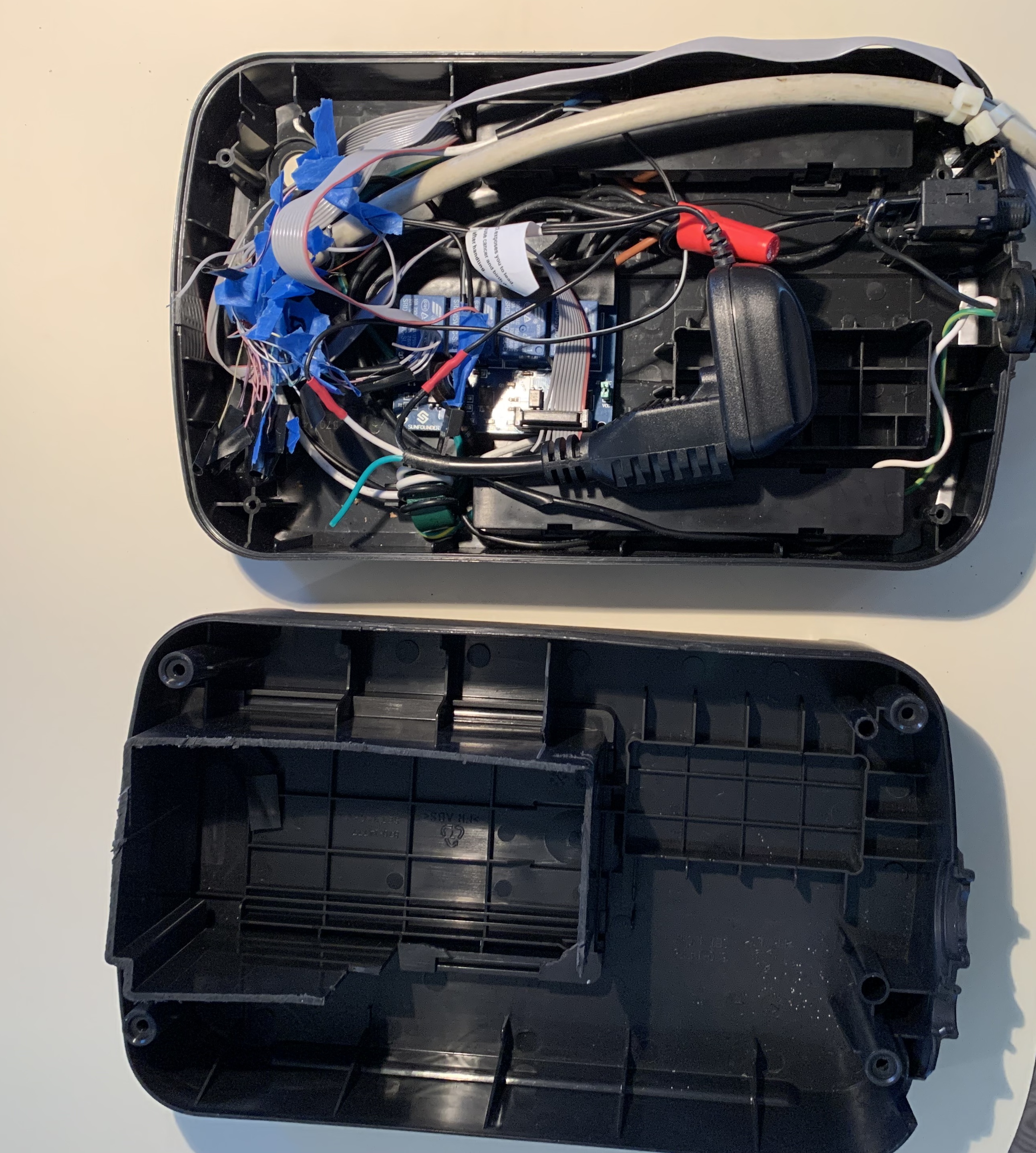 Another photo.
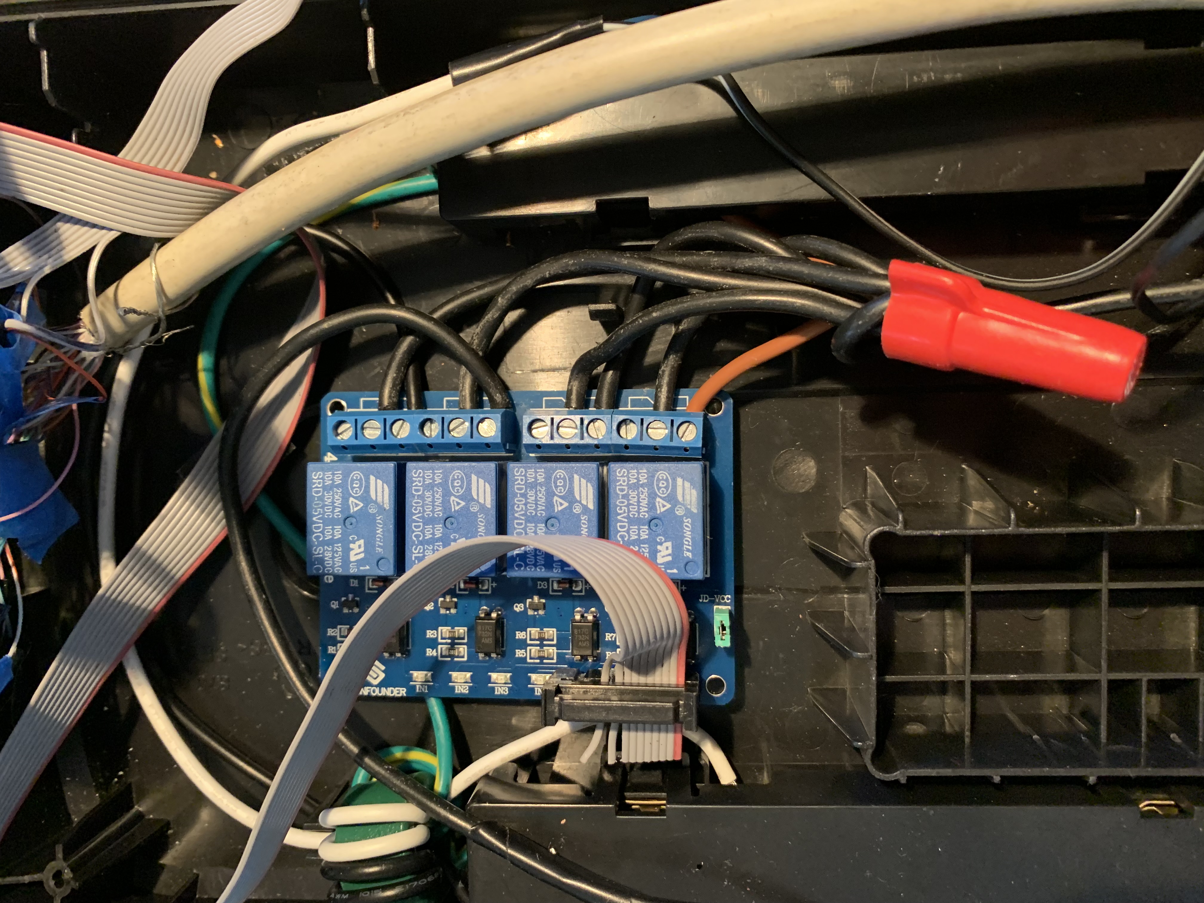 Closeup of relay board "Mains"
wiring.
Closeup of relay board "Mains"
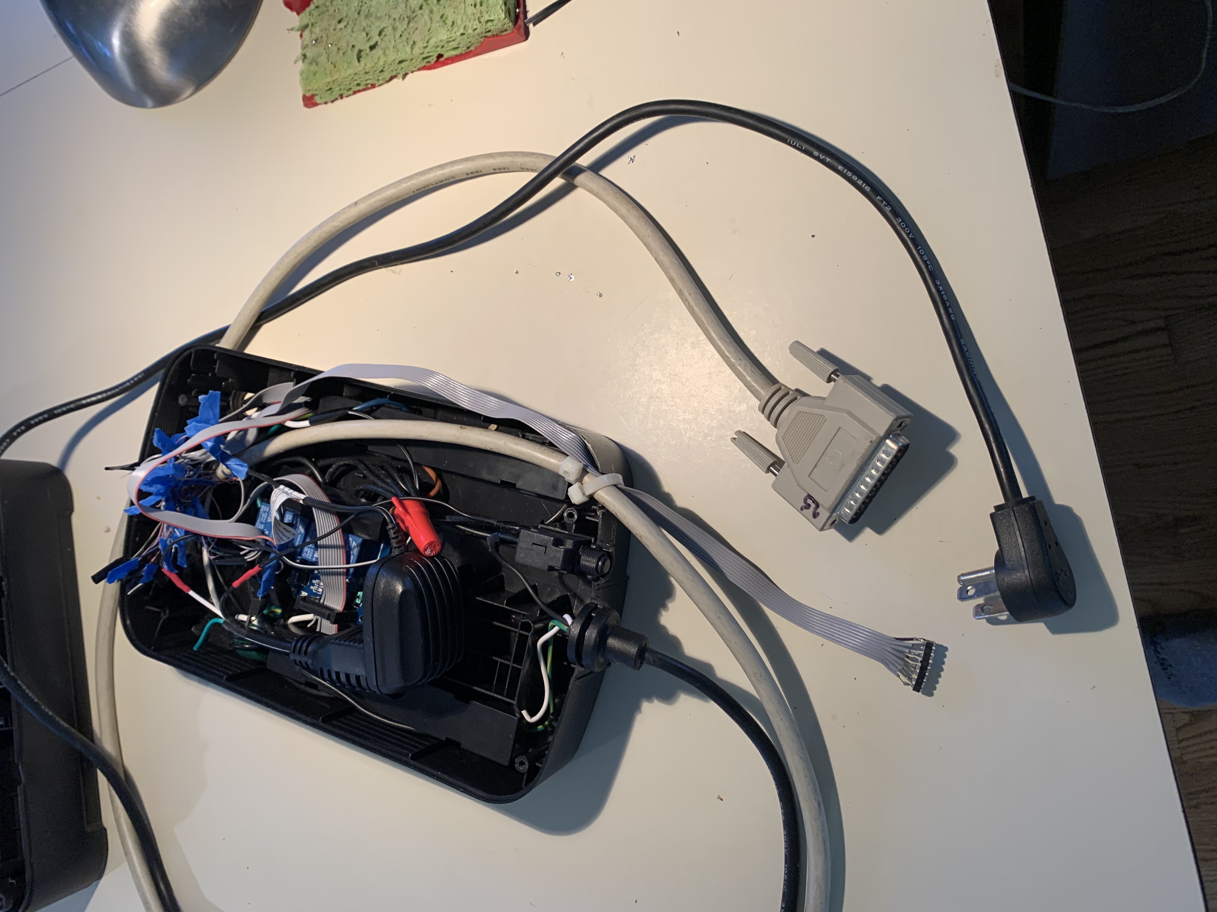
wiring. Parallel port connector.
 Final version, redone with RPi. No
more DB-25 cable. RPi uses WiFi for connectivity, but if
necessary, an RJ-45 ethernet cable could be run out the ribbon
cable hole. This RPi is an older Canakit 3B+ that I was given by
a friend; it's hidden underneath the ribbon cable junction. Relay
board is just visible under that.
Final version, redone with RPi. No
more DB-25 cable. RPi uses WiFi for connectivity, but if
necessary, an RJ-45 ethernet cable could be run out the ribbon
cable hole. This RPi is an older Canakit 3B+ that I was given by
a friend; it's hidden underneath the ribbon cable junction. Relay
board is just visible under that.suapt-get install xtermapt-get install x11-apps (for xload)apt-get install ftp (ftp client is not installed by default)apt-get install tcsh (my preferred shell)apt-get install emacs (my preferred editor)vipw update my usernumber, make sure group is staff (50 on raspbian)cd /home/[me]chown [me] . update to new usernumberchgrp staff .exitmkdir binftp [home domain]. Download the usual login files like .cshrc and .profile, and get the bin directory.
Obviously plug in screen, mouse, keyboard.
Power up.
Choose "noobs".
Wade through install.
Give it WiFi info, let it update.
Go into preferences->Raspberry Pi Configuration, click Interfaces tab, and enable SSH and I2C.
Start a command line.
sudo passwd root
Change root password to something you can deal with.
edit /etc/dhcpcd.conf
Comment in the sample static block and fix with your addr.
If you're using WiFi, don't forget to change to "wlan0" from "eth0".
Edit /etc/hostname and change to your full hostname and domain
adduser and create your personal account
shutdown -r now
Start a command line, enter ifconfig -a to confirm
Check for ssh from outside world. From here on out you can do everything via ssh and xterm, no more need for kbd/mse/mon on the pi itself.
I had assumed this would simply trigger off a set of output pins, but no, it uses the I2C bus.
[Note! See 22020319 above to do the following from command line.]
This requires additional setup at the console screen using the
default UI. I have been running headless for months, so I had to
dig up the micro-dmi/dmi adapter, borrow a screen/mouse/keyboard
from another computer, just to go in and enable this. (I'm sure
there's a way to do it from the commandline, but this was easier
than trying to figure it out.) See the following website:
wiki.52pi.com
EP-0099. In a nutshell, on the main screen Raspi desktop,
take Settings->Preferences->Interfaces. Find the I2C interface
option, hit Enable. It'll say "do you wanna turn on Arm
I2C?", take yes.
From this website, you'll find how to check for success:
Seeed
4 ch relay RPi Hat.
In a nutshell: use the following to verify success:
i2cdetect -y -r 1
You'll get a screen with
a grid that shows all your I2C devices, you'll only see the
one relay board you have installed, the rest will be "--". This
number is the offset your board is set at, mine defaults to 0x10
with no jumpers. Above EP-0099 doc explains how to change
this.
I then proceeded to try the other python libraries and test programs on the Seeed page, but was unable to get any to work. (Yes, I changed the hard-coded relay address in the code to match mine, but no relay activity.)
Next I tried the latter steps on the EP-0099 page,
and was able to make the relays trip.
In short (from superuser):
i2cset -y 0x10 0x01 0xff turn on rly 1
i2cset -y 0x10 0x01 0x00 turn off rly 1
i2cset -y 0x10 0x02 0xff turn on rly 2
etc. So now I know the hardware works, and I'm done with the
remote scrn/kbd/mouse and can go back to ssh/x-windows.
Note that in the end, I decided not to change over to this board
for the project. I already had the existing relay board in place
and had the mains connections wired into the box, and the software
was already able to control it. It wasn't worth the effort
to mechanically remount and rewire the new board, and I'd
have to get the software working doing I2C. I'll get to that
someday, and use this board for some other future project.
RPi::WiringPi to work. Am having problems installing. Now trying:
	use strict;


use HTTP::Daemon;

use HTTP::Status;

use HTML::Entities;


use Net::Domain;

use HTTP::Date;

use HTTP::Request;

use LWP;

use JSON;

use Net::SMTP;

use URI::Escape;

use URI::Encode qw(uri_encode uri_decode);

use Digest::SHA qw(hmac_sha256);

use MIME::Base64;

use Date::Parse;

use Sys::HostAddr;


use Errno qw(EAGAIN EIO);

use Socket;

use Net::Ping;

use IO::Socket;
 (click on image for full-size image)
MetaCpan RPI::Pin documentation.
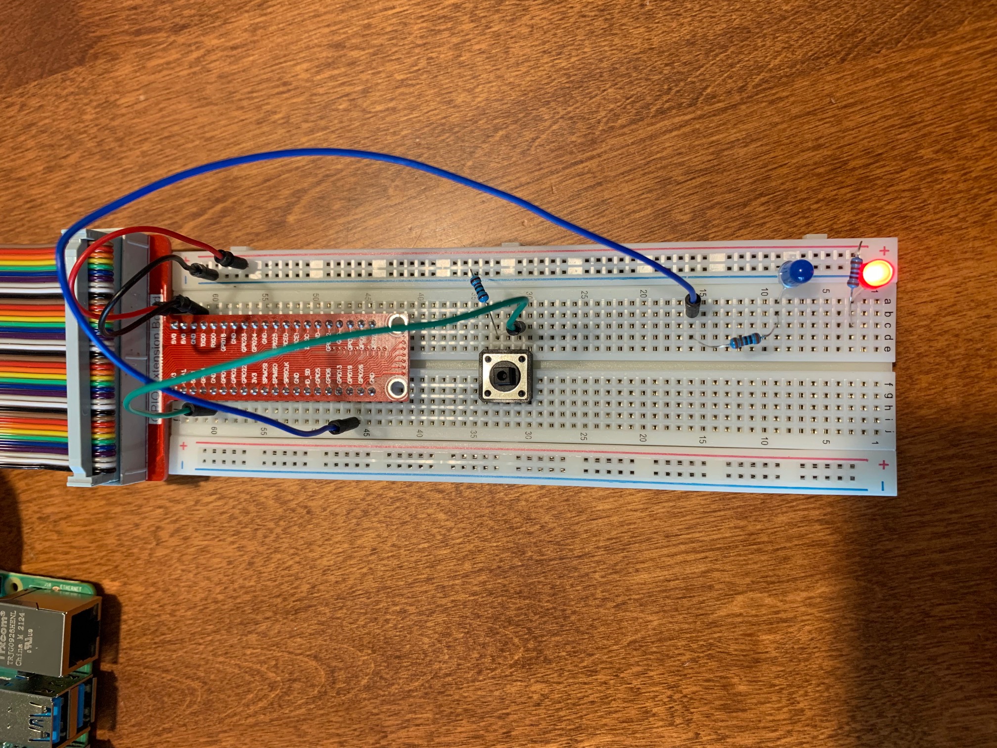
Click here for my gpiotest.pl simple demo program.
This demonstrates toggling an output (blue LED and you can hear relay clicking), polling style read, and interupt on input change. These actions are independent - the button push is only displayed on the computer screen, the relay and blue led are simply toggling at 1 second interval. Red LED simply indicates power connected.
Here's a 21 sec video showing program in action. Notice the keybounce the second time I release the button - two entries into the interupt handler. This is something that you'll have to be able to handle in your code as this can easily happen in the real world.
So there's the basics of the input/output control functions, now
it's up to you to write the code to do what you want!
cd ~mkdir bcm2835cd bcm2835wget http://www.open.com.au/mikem/bcm2835/bcm2835-1.59.tar.gztar xvfz bcm2835-1.59.tar.gzcd bcm2835-1.59/./configuremakemake installapt-get install wiringpicpan -i Device::BCM2835cpan -i WiringPi::APIcpan -i RPi::Pin
      use RPi::Pin;

      use RPi::Const qw(:all);

      my $pin = RPi::Pin->new(4);

      $pin->mode(INPUT);

      $pin->set_interrupt(EDGE_RISING, "main::pin4_interrupt_handler");

      while (1) {

              my $num = $pin->num;

              my $mode = $pin->mode;

              my $state = $pin->read;

              print "pin number $num is in mode $mode with state $state\n";

              sleep(1);

      }


      sub pin4_interrupt_handler {

              print "in interrupt handler\n";

      }
At this point you no longer need the scrn/kbd/mouse, everything can be done via command line ssh and x-windows with putty on your PC.
NOTE! If you're using an external relay board, see above 20220308 notes.